Need to depressurize a machine before changing a hose, valve, or Replacement Hydraulic Cylinders? The safe method is to stop the power unit, block or lower the load, isolate every energy source, discharge the accumulator, and verify zero pressure with a rated gauge. This guide explains how to depressurize hydraulic cylinders, mobile equipment, presses, and industrial power units using lockout/tagout, hydraulic fluid isolation, and pressure verification. It also covers trapped pressure, thermal expansion, and practical service cases so a technician can work without relying on guesswork.
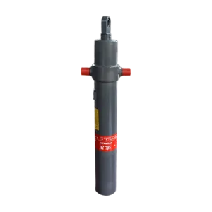
A hydraulic system can remain dangerous after the electric motor has stopped. Oil may be trapped between a directional control valve and a cylinder, an accumulator may still contain stored energy, or a suspended load may be supported only by hydraulic pressure. A system operating at 210 bar (3,045 psi) can exert approximately 21,000 N on a 100 mm-diameter piston, before considering gravity, friction, or mechanical leverage.
Depressurization is therefore more than switching off the pump. The technician must remove pump pressure, isolate the energy source, control the load, bleed stored pressure, and confirm the result. The same principle applies when installing Jiaheng Replacement Hydraulic Cylinders or replacing a hydraulic hose.
Suspended loads: A boom, platen, fork, or attachment can fall when a valve is opened.
Accumulator energy: A bladder, piston, or diaphragm accumulator can retain gas-charged energy after shutdown.
Blocked-in oil: Oil between closed valves can remain at operating pressure.
Thermal pressure: Heating trapped oil can increase pressure even when the pump is off.
Pilot and servo circuits: Small control lines can retain enough pressure to move a large actuator.
Injection injury: A pinhole leak can penetrate skin and cause a medical emergency without appearing severe externally.
Prepare the following before touching a fitting or cylinder port:
Machine-specific hydraulic schematic or service manual
Lockout/tagout locks, tags, and isolation devices
Safety glasses with side protection and a face shield when opening connections
Oil-resistant gloves and protective clothing
Steel-toe footwear
Calibrated pressure gauge with a working range suitable for the circuit
Correct test-point adapter or diagnostic hose rated above the maximum system pressure
Approved bleed hose or drain container
Two-way communication equipment when another person is controlling the machine
Mechanical blocking devices, cylinder locks, stands, or cribbing
Absorbent pads and a spill-control kit
Correct replacement seals, plugs, caps, and fittings
Do not use a pressure gauge whose maximum scale is lower than the circuit rating. As a practical measurement rule, select a gauge that places normal working pressure near the middle of its scale, commonly around 50% to 75% of full scale. Confirm the gauge, hose, adapter, and test point have compatible pressure and temperature ratings.
Read the equipment manufacturer’s shutdown procedure.
Identify the pump, motor, accumulators, counterbalance valves, pilot circuits, and all cylinders connected to the circuit.
Determine whether the load can move when pressure is removed.
Inspect the hydraulic schematic for multiple pressure sources or parallel circuits.
Tell nearby workers that the machine will be isolated.
Allow hot oil to cool. Hydraulic oil above approximately 60°C (140°F) can cause serious burns and may produce pressure from thermal expansion.
Use the hydraulic schematic, pressure gauge, mechanical supports, and lockout devices before servicing Replacement Hydraulic Cylinders.
Move the machine to a level, stable location when the operating procedure allows it. Place mobile equipment in the manufacturer’s service position, set the parking brake, chock the wheels, and remove unnecessary personnel from the danger zone.
For loaders, cranes, presses, lift tables, and other machines with elevated components, lower the attachment to the ground if possible. If lowering is not possible, install rated mechanical supports. Never rely on a hydraulic cylinder, hose, check valve, or counterbalance valve as the only support for a raised load.
Return controls to the neutral position, stop the hydraulic pump, and switch off the prime mover. For an electrically driven power unit, use the normal stop control first so the system does not stop under an unexpected command.
Do not assume that a quiet pump means zero pressure. The motor may be off while an accumulator or blocked-in circuit remains charged.
Isolate the electrical disconnect, engine ignition, battery source, or other prime-mover energy source. Apply a personal lock and tag according to the site’s lockout/tagout procedure. If the machine has remote controls, disable them as well.
Where several workers are involved, each worker should apply an individual lock. Test the start control after isolation, then return the control to the off or neutral position. The test confirms that the machine cannot restart; it does not by itself prove that hydraulic pressure is gone.
Lower the cylinder to its safest position using the manufacturer’s normal control procedure before isolation, if this can be done safely. On a press or lift, install a physical support capable of carrying the full load with a suitable safety factor.
When servicing a Jiaheng Replacement Hydraulic Cylinders installation, confirm whether the cylinder is single-acting, double-acting, telescopic, load-holding, or equipped with a pilot-operated check valve. A double-acting cylinder can retain pressure on both the cap end and rod end.
Use the designated pressure-relief or unloading control specified by the machine manufacturer. Some systems are depressurized by moving the directional valve through all positions with the pump locked out; others require a manual bleed valve or test-point connection.
Move the control slowly and deliberately. If a control causes movement, stop immediately and reassess the mechanical support and isolation procedure. Do not force a stuck valve and do not loosen a hose or fitting to “make” pressure escape.
Locate every accumulator shown on the hydraulic schematic. Close the isolation valve only when the manufacturer’s procedure permits it, then open the approved accumulator bleed valve slowly. Monitor the pressure gauge until the hydraulic side reaches the specified safe condition.
Hydraulic-side pressure of zero does not automatically mean the accumulator is safe to remove. The gas side may still be charged with nitrogen, often at a precharge specified by the equipment manufacturer. Never use compressed air or oxygen to charge a hydraulic accumulator. Accumulator inspection and gas-side discharge should be performed by trained personnel using the correct charging kit.
For a double-acting cylinder, verify both ports. The cap-end port and rod-end port may be isolated by separate valves, pilot checks, or counterbalance valves. Bleed each side through the manufacturer-approved test point or bleed circuit.
For a single-acting cylinder, check the return line, load-holding valve, and any pilot line. A return tank line may not be pressure-free if a filter is blocked, a check valve is closed, or the reservoir is pressurized.
Connect a properly rated gauge to the designated test point before opening the circuit, when the design allows it. Confirm that the reading has fallen to zero or to the manufacturer’s specified safe value. Repeat the check after waiting several minutes because pressure can rebuild when trapped oil migrates through a valve.
Operate the controls only as directed by the service manual and only after the load is mechanically secured. A gauge reading of zero at one test point does not prove that every branch, accumulator, pilot line, or cylinder chamber is depressurized.
Wait five to ten minutes, or the period specified by the manufacturer, and check the gauge again. If the pressure rises, investigate a charging accumulator, leaking check valve, trapped thermal energy, or a connected pressure source.
Do not continue disassembly until the pressure source is identified and isolated. For a blocked-in oil volume, the correct remedy may be a controlled bleed valve, a thermal relief valve, or a revised isolation procedure—not simply a looser fitting.
Place a drain pan below the connection, clean the area, and loosen fittings slowly while standing to the side rather than in front of the connection. If oil sprays, immediately retighten the fitting, stop work, and repeat the isolation and gauge verification process.
Cap and plug hoses and ports to prevent contamination. Mark the cap end, rod end, pilot line, and drain line before removal. Hydraulic contamination particles above approximately 4 microns can damage servo and proportional components, so clean plugs and lint-free materials are essential.
Install the cylinder, hose, seals, and fittings according to the manufacturer’s torque and alignment requirements. Keep the cylinder rod aligned with the load; side loading can damage rod seals, guide rings, and bearings.
Refill or top up with the specified hydraulic fluid, then remove air at the approved location. Start the pump at low-risk conditions and cycle the actuator slowly without a load when possible. Inspect for leaks using cardboard or wood, never with a hand.
After testing, confirm that the cylinder holds position, the pressure remains within the design range, and no hose, fitting, or seal shows leakage. Record the pressure reading, fluid type, component serial number, and work performed.
A maintenance technician preparing to replace a cylinder on a compact construction machine reported that the pump had been stopped and the control lever moved to neutral, yet the rod-end hose still released oil when the connection was disturbed. The problem was not a failed replacement cylinder. A pilot-operated check valve had isolated the rod-end chamber, leaving trapped pressure in that branch.
The corrected procedure was to mechanically support the attachment, lock out the power source, connect a rated test gauge to both cylinder ports, and use the manufacturer’s pilot-release procedure. The lesson is practical: depressurizing the pump outlet is not the same as depressurizing both chambers of a double-acting cylinder.
In another service situation involving a hydraulic press, the electric motor was off and the main gauge appeared near zero. A separate accumulator circuit still showed pressure because its isolation and bleed valve were not included in the first shutdown check. Once the accumulator was identified on the schematic and discharged through the approved bleed point, the pressure remained at zero during the waiting-period check.
This case demonstrates why a pressure map is useful. The technician should list every pump, accumulator, cylinder chamber, pilot line, and pressure-reducing valve before opening the circuit.
A service team replacing seals on a lift cylinder initially observed zero pressure at the test point. Several minutes later, the gauge rose again. The likely causes were investigated as a blocked-in oil volume and thermal expansion rather than treated as a gauge failure. The team stopped work, secured the lift mechanically, isolated an additional valve, and repeated the bleed-and-wait test.
The important measurement is not only the first gauge reading. A safe procedure also checks whether pressure returns after time, temperature change, or valve movement.
Why it fails: Stored energy may remain in accumulators, cylinder chambers, and isolated lines.
Solution: Apply lockout/tagout, support the load, bleed all identified pressure sources, and verify with a rated gauge.
Why it fails: A gauge may measure the pump outlet while a cylinder branch remains blocked in.
Solution: Check the cap-end port, rod-end port, accumulator circuit, pilot circuit, and any auxiliary pump or external pressure source.
Why it fails: High-velocity oil can cause injection injury, and the hose may whip when the fitting separates.
Solution: Use the engineered bleed valve or test point. Replace damaged bleed hardware before continuing.
Why it fails: A hose, seal, valve, or cylinder can fail without warning.
Solution: Lower the load or install rated mechanical blocking before pressure is removed.
Why it fails: The accumulator can maintain pressure after the pump stops and may contain dangerous nitrogen precharge.
Solution: Locate all accumulators on the schematic, bleed the hydraulic side as specified, and use qualified personnel for gas-side work.
Why it fails: A gauge with an unsuitable range can rupture or provide misleading readings.
Solution: Use calibrated instruments with pressure, temperature, fluid, and connection ratings that match the system.
Why it fails: A hydraulic injection injury can occur through a leak that is too small to see clearly.
Solution: Use cardboard, wood, or an approved leak-detection method and obtain immediate medical attention for any suspected injection injury.
Before installation, compare the old and new cylinder specifications. Check bore diameter, rod diameter, stroke length, retracted and extended dimensions, mounting style, port size, working pressure, test pressure, seal material, and operating temperature.
Confirm that the cylinder’s rated working pressure is equal to or greater than the machine’s maximum operating pressure. Also verify that the mounting pins, spherical bearings, clevises, and hoses are not worn. A cylinder with the correct stroke but incorrect retracted length can create a mechanical stop before the machine reaches its intended position.
After installing Jiaheng Replacement Hydraulic Cylinders:
Keep the rod clean during initial cycling.
Bleed trapped air according to the equipment procedure.
Cycle at low speed and low load first.
Inspect both ports and the rod seal for leakage.
Check alignment at full retraction and extension.
Record the operating pressure and temperature.
Stop immediately if the cylinder creeps, jerks, drifts, or develops abnormal noise.
Use this sequence every time:
Park the machine and control access to the work area.
Lower the load or install rated mechanical supports.
Stop the pump or prime mover.
Apply lockout/tagout and prevent remote restart.
Identify pumps, accumulators, pilot circuits, and both cylinder chambers.
Bleed pressure through approved valves or test points.
Verify zero pressure with a suitable gauge.
Wait and check for pressure rebuild.
Remove hoses or cylinders slowly while using spill control.
Cap ports, prevent contamination, and install the correct component.
Cycle and test the repaired system at low risk.
The central rule is simple: never open a hydraulic connection until the load is mechanically secure and every possible pressure source has been isolated and verified. If the schematic is unclear, the gauge reading is abnormal, or pressure returns after bleeding, stop the job and involve a qualified hydraulic technician.
Follow the machine manufacturer’s procedure. If no time is specified, wait several minutes after bleeding and then recheck the gauge. Waiting alone does not depressurize a system; it only allows time to identify pressure rebound or thermal effects.
Not always. Moving the lever may relieve pressure in one circuit while leaving pressure in a cylinder chamber, pilot line, accumulator, or blocked-in hose. Use the schematic and verify each relevant test point.
Secure the load, isolate the pump, lock out the machine, and bleed both the cap-end and rod-end circuits through the approved procedure. Check for pilot-operated check valves and counterbalance valves that may prevent pressure from escaping.
No. A fitting can release high-pressure oil suddenly, and a hose can move or whip. Use a designated bleed valve or test point. If no safe bleed method exists, have the circuit modified or serviced by a qualified professional.
The gauge should read zero or the manufacturer’s specified safe value at the relevant circuit. Check more than one point when the system has multiple branches. A zero reading at the pump outlet does not prove that a cylinder port is pressure-free.
It must match the required bore, rod diameter, stroke, mounting dimensions, port configuration, pressure rating, seal compatibility, and operating environment. A visually similar cylinder may be unsuitable if its pressure rating or dimensions differ.
Stop work, keep the load mechanically supported, and investigate accumulators, connected circuits, leaking check valves, thermal expansion, and external pressure sources. Do not continue loosening fittings until the pressure source has been isolated and the zero-pressure test remains stable.
Seek emergency medical treatment immediately, even if the wound looks like a small pinprick and pain is limited. Tell medical personnel that hydraulic fluid may have been injected under pressure. Do not delay treatment to finish the repair.



Comments
0